Use Case Diagram
Intro
Use Case Diagrams are used to visualize different types of users in a system and how those users interact with the system. It provides a higher-level view of the system.
A single use case diagram captures a particular functionality of a system. So to model the entire system, a few major use cases are used. A Use case diagram should not go deep into the details of use cases rather it should be easily understood by any non-technical person. To describe any use case in detail, we can link the use case to another diagrams (such as activity diagram or sequence diagram).
Use Case Diagram objects
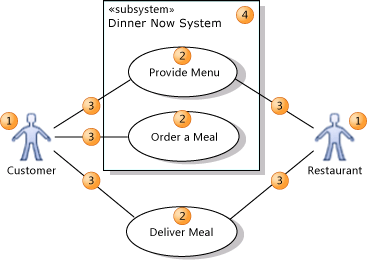
- Use cases : A function or an action within the system. i.e, order a meal.
- Actors : Users that interact with the system. It can be a person, an organization, or an outside system. i.e, customer, restaurent.
- System : Whatever we are developing. it might be the enitre application or any particualr functionality. i.e, meal delivery system.
Relationships
- Association : Association indicates that an actor takes part in a use case. i.e, Customer Orders a Meal.
- Generalization : Generalization relationship is similar to inhertince in OOP concepts. We can use this relationship when two or more use cases have common behavior. The parent use case is specialized into two or more specialized child use cases. i.e, Pay use case can be specialized into two child use cases Pay by Credit Card and Pay by Cash.
- Include relationship : Include relation shows how a use case breaks into smaller use cases. An included use case is a step that the actor might have to perform to achieve the overall goal of the including use case. An included use case can be shared by multiple use cases. i.e, ‘Order a Meal’ and ‘Book a Restaurent’ both use cases may include an included use case called ‘Pay’. more details
- Extend relationship : One use case may add functionality to another use case under certain circumstances. more details
How to Draw
We should first identify actors, use cases and their relationships(both include & extend). and then we will start drawing the diagram
- Actors are represented by stick figures.
- Use cases are represented by ovals.
- Assosiations are represented by a line between the actor and use case.
- Generalization realations are represented by a line with an arrow between the use cases. The arrow should point at the parent use case.
- Include relations are represented by dotted line with an arrow between the including use case and included user case. The arrow should point at included use case.
- Extend realations are represented by a line with an arrow between the use cases. The arrow should point at the main use case.
Example

source : msdn